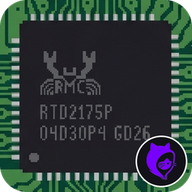
How to install the interposer on the PS5 Slim
Step by step to replace the Realtek RTD2175P HDMI chip with the Nuvoton/Panasonic MN864739 using the Interposer Tech MeoW and PS5 HDMI Tool.
Who this guide is for. Advanced bench and microsoldering technicians. It does not teach rework technique and is not an introductory soldering tutorial. Without the preparation below, the risk of destroying the motherboard is high.
- Experience in SMD/QFN microsoldering, with hot air and a precision iron.
- Knowledge of SPI NOR reading and writing: CH341A programmer, dumps and a backup before writing.
- A bench with ESD protection, good lighting and a microscope or magnifier.
- The Interposer Tech MeoW itself: it is made for this fit, and you cannot improvise wiring straight to the chip.
What the interposer does
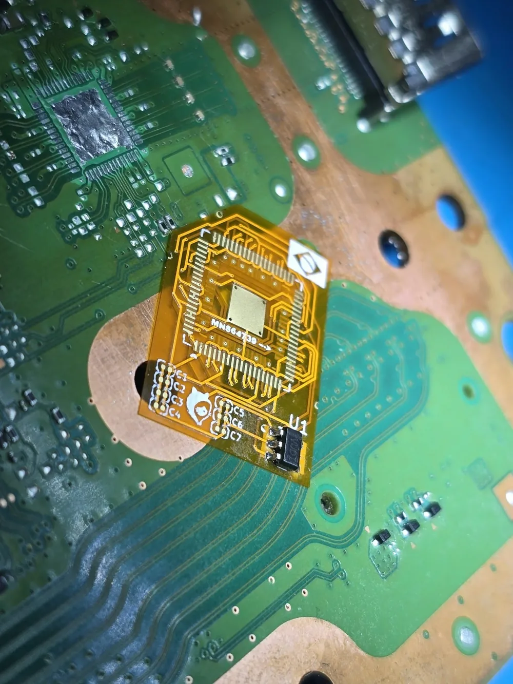
It replaces the original Realtek RTD2175P with an MN864739 without redesigning the motherboard traces. The bottom side has the RTD2175P footprint and is soldered onto the same pads where the Realtek was. The top side has the MN864739 footprint, where the new chip is soldered. Capacitors C1 to C7 and the U1 regulator come already mounted.
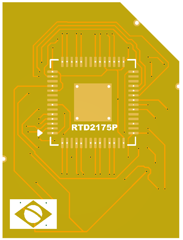
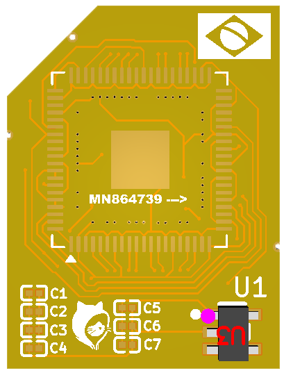
Pin 1: both sides have a triangular mark in the same corner. Always align it with the pin 1 indicator of the original footprint and with pin 1 of the MN864739. The MN864739 ---> arrow shows the mounting direction of the new chip.
Why the 1.8 V regulator matters
The MN864739 needs 0.9 V and 1.8 V. The RTD2175P it replaces needs 0.9 V and 3.3 V, and that 3.3 V trace already exists on the board. The U1 (TI TLV71318PDBVR) regulator takes that 3.3 V and steps it down locally to 1.8 V.
This way the interposer does not need to pull 1.8 V from another point of the motherboard. The HDMI chip is one of the parts that fail most in the PS5 video section: if the 1.8 V came from another point, such as the CXD PMIC (southbridge), an overload would have a free path to reach that circuit too. With the regulator on the part itself, that failure path stays contained there.
The regulator EN pin is on the 0.9 V trace: the 1.8 V output only rises once the 0.9 V is present, with no external component. This matches the TI datasheet: EN turns on from 0.9 V and turns off below 0.4 V.
| TLV71318PDBVR (SOT-23-5) | Value |
|---|---|
| Output voltage | Fixed 1.8 V |
| Input range | 1.4 V to 5.5 V |
| EN pin, on (minimum) | 0.9 V |
| EN pin, off (maximum) | 0.4 V |
Interposer test point map (PDF)
Documentation with some of the board's test points, without and with the interposer, the color code, the interposer layout and the 1.8 V regulator schematic. There are more points: the full diagram will be available soon.
Tools and supplies
| Item | What for | |
|---|---|---|
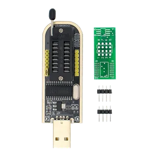 | CH341A programmer | Backing up and writing the SPI NOR, before and after the swap. |
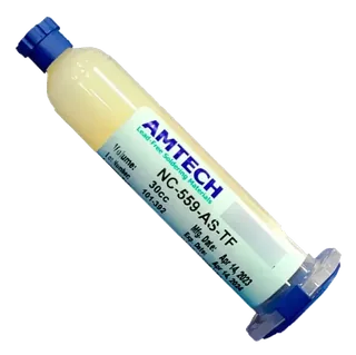 | Amtech NC-559 flux | Removing the RTD2175P and reflowing the interposer and the MN864739. |
 | 183 °C solder paste | Low-temperature alloy, so the neighboring components are not stressed. |
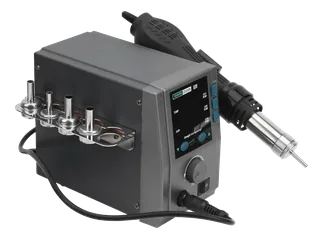 | Sugon 2020D hot air | Removal and reflow. Profile according to your bench calibration. |
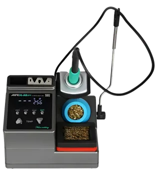 | Aifen A9 Pro iron, C210 tip | Precision touch-ups and pad cleaning. |
You also need the Interposer Tech MeoW, an MN864739 and a computer with PS5 HDMI Tool.
Where the HDMI chip is on the PS5 Slim board
The RTD2175P sits between the APU (SIE CXD90069GS) and the HDMI connector, in an area with plenty of exposed copper around it.
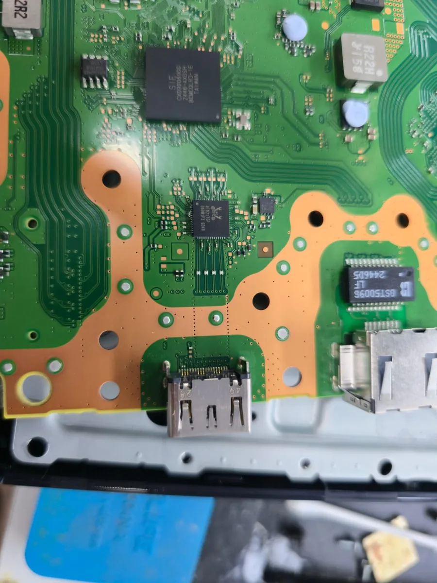
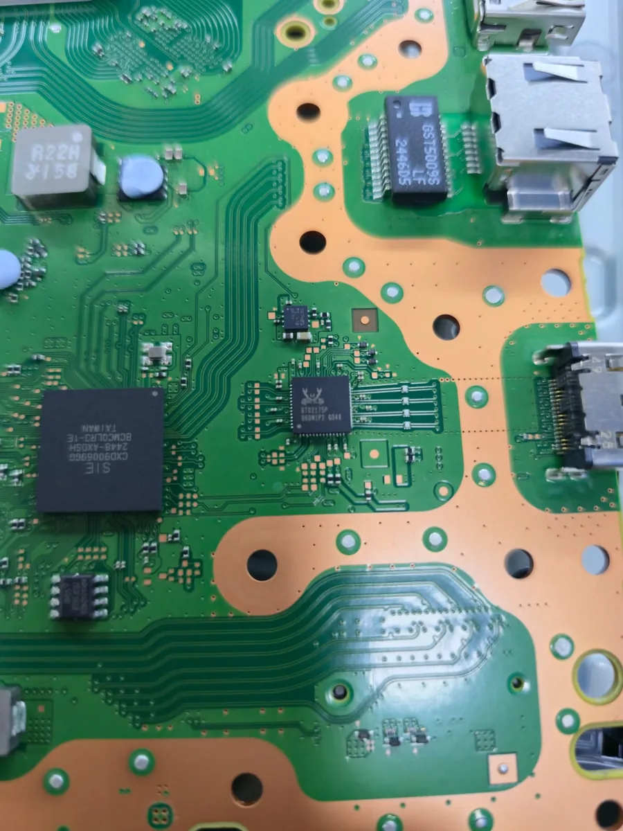
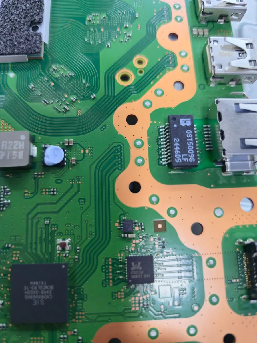
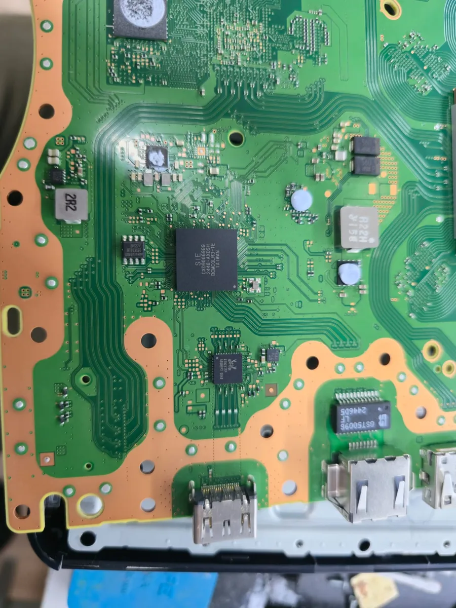
Confirm the RTD2175P marking on the chip itself before desoldering. Do not rely on the position alone, especially on a board that has already been reworked.
Procedure
The steps alternate between software and soldering. Follow the order: writing the NOR at the wrong time is the most common cause of a blue screen with no video after the conversion. The program buttons are named as they appear with the program in English.
1. NOR backup, before anything else
- Connect the CH341A to the NOR, still with the original RTD2175P, and open PS5 HDMI Tool on the CH341A Reader tab.
- Click 1. Detect CH341A reader and then 2. Read NOR. The program reads twice, compares and saves
DUMP1.binandDUMP2.bin. - If the reads do not match, the program warns you and saves nothing: redo the reader contact before going on.
2. Generate the conversion, still without soldering
- Under 3. Apply patch (HDMI chip), choose nuvoton and click Apply patch. This button only prepares the file: it does not write anything to the board yet.
- The program saves
REALTEK_FOR_NUVOTON.binnext to the backup. This is the file you write after the physical swap. - Check the log to see whether the checksum came out as resolved. If it came out as not resolved, stop and talk to us before going on with a customer's board.
- Do not click Write to NOR yet.
3. Remove the RTD2175P
- Protect the neighboring components with Kapton tape.
- Apply plenty of flux over the chip and remove it with hot air, using your bench profile for fine-pitch QFN.
- Clean the pads with the iron until they are flat and free of excess solder.
4. Install the interposer
- Apply a thin layer of 183 °C paste on the clean pads.
- Place the part with the RTD2175P side down. The flex is transparent: align it by looking at the pads underneath and check the pin 1 mark.
- Reflow until all pins are wetted. The small holes in the flex also let you solder by capillarity with the iron. Inspect: no bridges and no lifted pins.
- Let it cool down before handling.
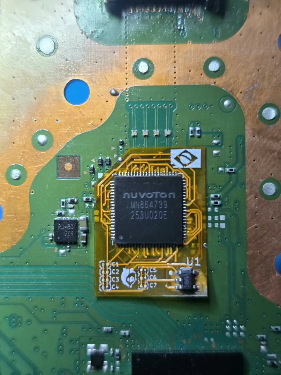
5. Solder the MN864739 on the interposer
- Apply flux and 183 °C paste on the top side.
- Place the chip following the arrow and the pin 1 mark.
- Reflow with lower temperature and airflow, so the part that is already fixed does not shift.
- Touch up individual pins with the iron if needed.
6. Inspect before powering on
- Look at both solder layers under magnification: board to interposer and interposer to MN864739.
- Test continuity and shorts with the multimeter between neighboring traces and against ground.
7. Write the converted NOR and test
- Connect the CH341A to the NOR again.
- In the program, use Load .bin file to write... and select the
REALTEK_FOR_NUVOTON.binfrom step 2. That is the right file, not an old backup. - Confirm the write (the program asks for a double confirmation and for you to type the word
GRAVAR, the same in every language) and wait for the 4 stages: check, erase, write and verify. - Power on the board and test the HDMI output.
Common problems
- No video, but the console powers on normally: suspect the soldering first (cold joint, bridge or shifted chip) before touching the NOR again.
- Hangs on the blue check screen: make sure the conversion checksum came out as resolved for this board's Wi-Fi revision.
- The CH341A does not detect the NOR after soldering: look for a short or a cold joint on the interposer pads before suspecting the programmer. Flux residue there can affect other lines of the board.
Legal notice
This procedure modifies the hardware, voids the console's factory warranty and carries a real risk of permanent damage to the motherboard if done incorrectly. The part and this documentation are offered with no guarantee of the repair result, and whoever does the work is responsible for it. This does not remove any rights the law grants to consumers.